HW-685 4-20mA Current Sensing
The HW-685 4-20mA Current Sensing Module documentation is work in progress. I will publish more comprehensive docs about this soon.
Overview
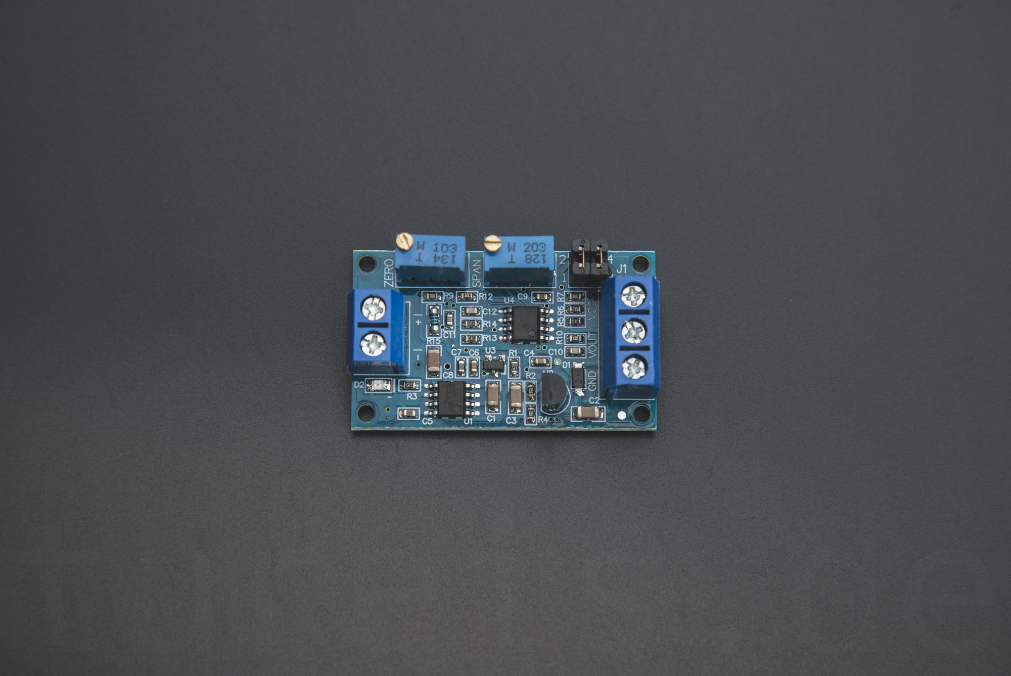
The HW-685 4-20mA Current Sensing Module
With this module you can measure currents from 4-20mA. It ‘translates’ the measured current into voltage. With two jumpers you can define the voltage output range. Also the module has two potentiometers for calibrating the zero and maximum voltage.
Connection
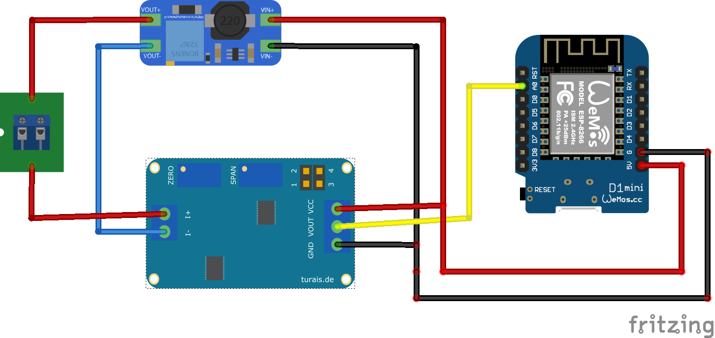 Example connection of the HW-685 module.
For a connection you need a constant voltage power supply. Connect the module like so:
| Wemos D1 Mini PIN | HD-685 | Remarks |
|---|---|---|
| 5V | VCC | 5V - 12V constant |
| G | GND | Ground |
| A0 | VOUT | Analog In |
| HD-685 | Remarks |
|---|---|
| VCC | 5V - 12V constant |
| GND | Ground |
| VOUT | Analog In |
| I+ | Positive Current In, after your sensor. |
| I- | Current out. Usually you connect this to GND. |
Attention
The VCC should be constant, otherwise the output voltage will change with the supply voltage.Usage
Before you can measure reliable results, you need to calibrate your module with the two potentiometers. For this you need a constant current. I used a trim-potentiometer with an multimeter in current sensing mode, this is not optimal but I did not have any other method at hand. You can also use a dedicated “Signal Generator”. They are fairly cheap on Aliexpress or Amazon.
Setting the Output Voltage
First you have to set the desired maximum output voltage for your VOUT.
Most microcontrollers don’t ‘like’ more than 5V, be sure to check that out. For example
if you use an Arduino it is okay to use 5V as your maximum voltage for your ADC.
| Voltage Range | Jumper Setting | Remarks |
|---|---|---|
| 0 - 3.3V | [ _ | _ ] |
“1-2” empty, “3-4” empty. |
| 0 - 5V | [ X | _ ] |
“1-2” connected, “3-4” empty. |
| 0 - 10V | [ X | X ] |
“1-2” connected, “3-4” connected. |
Calibrating the Module
-
Turn all potentiometers to the left. You’ll hear a little click if the leftmost position is reached. This may take a while.
-
Connect you constant voltage power supply to
VCCand a Multimeter toVOUT. -
Connect your 4mA current source in series to
I+andI-. -
Now turn the
ZEROpotentiometer to the right, until you reach a voltage you will later define as the 4mA point. -
Change the current source to 20mA and turn the
SPANpotentiometer to a voltage you will later define as the 20mA point.
For example with an Arduino you have an 10-Bit ADC. This means that the incoming voltage of your ADC input is divided in intervals. If you have an 10-Bit ADC these intervals will be 2^10 = 1024 values between 0 and 1024, therefore you have 1023 intervals.
In your Arduino you read an analog values as follow:
int analogPin = A3;
float read_voltage = 0.0;
float ref_voltage = 3.3;
float adc_intervals = 1023.0;

void setup() {
    Serial.begin(9600);
}

void loop() {
    read_voltage = analogRead(analogPin) * (ref_voltage / adc_intervals);
    Serial.println(read_voltage);
}
Code
Libraries
No Libraries needed.
Example
#include <Arduino.h>

int analogPin = A0;
float read_curr_ma = 0.0;
float max_curr_ma = 20.0;
float adc_intervals = 1023.0;


void setup() {
  // put your setup code here, to run once:
  Serial.begin(9600);
}

void loop() {
  // put your main code here, to run repeatedly:
  read_curr_ma = analogRead(analogPin) * (max_curr_ma / adc_intervals);
  Serial.println(read_curr_ma);
}
Example on Github
You can find the GitHub example here.
Blynk Example
#include <Arduino.h>
#define BLYNK_PRINT Serial
#include <ESP8266WiFi.h>
#include <BlynkSimpleEsp8266.h>

char auth[] = "YourAuthToken";
char ssid[] = "YourNetworkName";
char pass[] = "YourPassword";


int analogPin = A0;
float read_curr_ma = 0.0;
float max_curr_ma = 20.0;
float adc_intervals = 1023.0;

BlynkTimer timer;

void timer_event() {
  read_curr_ma = analogRead(analogPin) * (max_curr_ma / adc_intervals);
  Serial.println(read_curr_ma);
  Blynk.virtualWrite(V5, read_curr_ma);
}

void setup() {
  Serial.begin(9600);
  Blynk.begin(auth, ssid, pass);
  //Blynk.begin(auth, ssid, pass, "blynk-cloud.com", 80);
  //Blynk.begin(auth, ssid, pass, IPAddress(192,168,1,100), 8080);
  timer.setInterval(1000L, timer_event);
}

void loop() {
  Blynk.run();
  timer.run();
}
Buy
The following links are so called affiliate links. If you click on that link and buy a product, I'll get a small amount of commission. There will be no additional costs for you :)
comments powered by Disqus